" E-Recto "
DIY High Gain, 2-channel tube-amplifier (Mesa Boogie Dual Rectifier '94 "Light")
Poweramp, Power-Supply
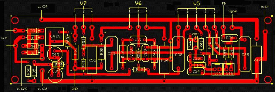
The poweramp is a classic PP-AB circuit. A lot of books were written about this topic, longer, better, deeper than i could ever explain. So i take the freedom to skip the part of a functional description and step straight to the layout. To the left and in the middle you can see the sockets for the power-tubes. The smaller one to the right is the socket for the phase- inverter-tube. The board itself can also be split logically into three parts, the left one contains the power-supply circuit (diodes, bias-pot, check-terminals), the middle one contains parts belonging to the power-stage, the right one handles the PI. NOTE that the rectifier-circuit used for the V1A-heating is located on the switching-matrix-PCB.
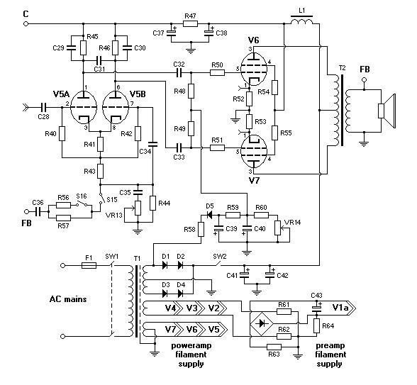
As i said earlier, the poweramp is an exact copy of the original with some of the provided switches being disabled. Because "ORANGE Clean" was disabled, S16 is free of any function and is permanently OPEN (study "switching matrix"). If you do not need "ORANGE Clean" at all, you can remove S16 together with R56. T2 is a Hammond-"allround"-product (1650P was not available, i replaced it by 1650K (50W/3.4K)). Loading the 4 Ohm-tap by 8 Ohm (box) you would obtain ca. 6.8K what is considered to be within a "good" range for a 6L6 PP pair. Some tone-variations are certainly possible by trying a different brand. Acoustically, no "good" or "bad" here, since tone is something very subjective. !
L1 is also a Hammond-product. I used 193G, (10H/150mA), yeah, an overkill, but yet again, the smaller one wasn't available and the "bigger" one was offered to me by Dirk to the same price, so i didn't refuse. 193G does its job pretty well inside my 50W-cube, but it can also be used for most of the 100W (and probably even for 150W) DIY-amps without any problems.
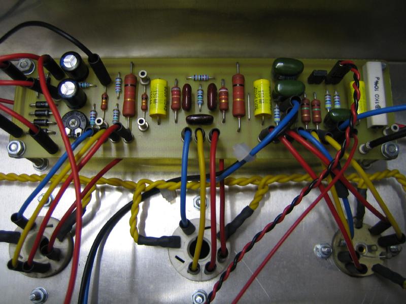
Worth mentioning, for R54/55 i recommend 3W metal-oxide instead of >=5W ceramic-coated-resistors. Better pulse-resistance, not flammable and cheaper. Originally, i used the latter ones, but after playing for a couple of hours, one of them died pretty suddenly, and after replacing both of them by MOs i have never had any problems.
T1 is a home-made power-transformer. Specs: B+ voltage (idle) 325V, max. current (DC) ca. 180-190 mA, 6.3V/1.5A preamp-, 6.3V/2.5A poweramp-heater, primary/secondary-screen. 325V would produce ca. 410-420V anode-voltage (load), thus a tick too low for "real" 50 Watt out of a 6L6 GC-pair. I would recommend a slightly higher B+ voltage in the range of 350 V (rate your parts, especially caps properly!). Doing this, you probably will also need to adjust the filter-resistors slightly, if you want your anode-voltages to stay close to the original. Many manufacturers assure, voltage-variations of 20% are negligible, well, still...:-).
C41-C42, C37-C38 are high-voltage-caps (depending on
the power-transformer used, at least 500V, CALCULATE !). I used two JJ multi-cans (32+32). All elements (with exception of T1, T2, L1, caps and controls) are found on the PCB. For particular values consult original schematics.
"The placement
map". ([UPDATE]: for 6L6 GC R52, R53 are connected to the Pin 8).